Hi Jim
I'd rather get it right than rush things, so I am happy wait to hear from you. I really do appreciate the extra effort you are taking to assist.
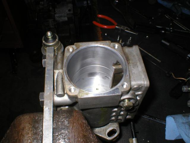
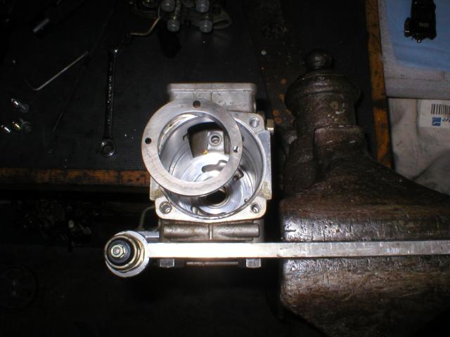
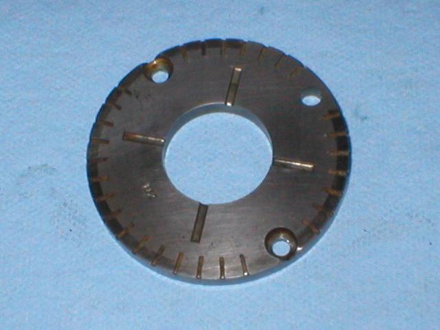
This paragraph is a later addition, but rather than place it at the end, I've edited it in here. I was speaking with a pug parts supplier today and he put me on to a retired diesel mechanic and I was able to get a few answers from him which I'll share here. Rather than put you to the trouble of stripping down your spare pump, I think these answers might serve both our curiosities.. He did say that of the hundreds that he had done that he never had to replace a drive coupling spring or a distributor head body. I guess that we can take that as both these items in my pump being ok. He did labour on the importance of post rebuild recalibration and correct assembly. In relation to assembly he also mentioned that the lift pump outer ring was cambered for left or right direction of rotation and to be carefull of correct orientation with that in mind.
I know when I sent the parts away to be cleaned that I had them in the correct orientation, plus there was a tarnish witness mark on the bottom of the ring confirming its seating position. On return however the ultrasonic cleaning had removed the witness mark and I can't see a noticable camber on the pumping surface of the rotor ring to be sure of its orientation. Have you heard of this and do you know how I can double check this?
He didn't seem too worried about the mention of the wear mark on the lift pump pressure plate or cross coupling. He said it wasn't usually there but if it bottomed out it would be. Otherwise no biggy in the scheme of things. I also mentioned the drive shaft end float and as you mentioned he asked about the housing bushings but assuming they were good some end float was ok.
Moving on; Thinking back to the lateral movement of the front shaft that I mentioned earlier in this thread, it would be occuring in the drive coupling spring area. Other than the drive shaft thrust plate there doesn't appear to be another mechanism short of the spring, the drive coupling and the thrust washer to limit the drive shaft from floating back a bit when turned with the tension of the cam belt attached. I recall that I wasn't able to duplicate the movement when the pump had been removed from the car.
The pump is currently assembled up to the lift pump, pressure plate and roller cage and with the roller cage held down firm in the casing I was able to measure close to .4mm of float in the drive shaft using the side face of governor drive gear as my reference.
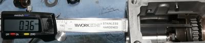
The only way I can see to reduce that clearance is to fit a thicker thrust plate. From what I can see, the roller cage is going to move from side to side with some possible lateral movement as well when the timing piston aticulates. In theory then this will allow the drive shaft to move a little more as well. Yes / No?
When I measured the combined movement (i.e. roller cage and drive shaft included) I got close to 1.5mm of end float.
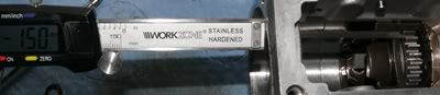
That additional lateral movement is of course coming from the oval connecting pin slot to the timing device in the bottom of the housing. I can't see any way to reduce that clearance.
Seeing now how these pumps are put together I'm wondering if that end float at the sprocket (when on the car) might be normal? There would be an inherent clearance created by the drive coupling spring. My theory is that as the spring is compressed via the cam plate, the clearance, or part thereof, is taken up to accomodate the travel and to maybe serve as a damper. This same clearance would also allow the shaft to float back and when the shaft and the cam plate take up all the clearance that point is where the cross coupling and the drive shaft dog drive touch and hence the witness marks and maybe the clicking noise as well. Your thoughts?
Cheers
Ron