Hydractive Repair Kit Fitted.

This is the Forum for all your Citroen Technical Questions, Problems or Advice.

Moderator: RichardW

Post Reply
User avatar
CitroJim
A very naughty boy
Posts: 49658
Joined: 30 Apr 2005, 23:33
Location: Paggers
My Cars: Bluebell the AX, Polly the C3 Picasso, Pix the Nissan Pixo, Propel the duathlon bike, TCR Pro the road bike and Fuji the TT bike...
x 6204
Contact:

Hydractive Repair Kit Fitted.

Post by CitroJim »

I have received and fitted the Activa-specific Hydractive Repair Kit now offered by Roy at E-Crofting. This kit was discussed at length here:

http://www.frenchcarforum.co.uk/forum/v ... hp?t=21720

The kit arrived very promptly, well packed and most professionally presented. The kit included the unit itself, a set of Scotch-Loks and an adhesive pad. Following criticism of Scotch-Loks in the original thread, Roy included a set of an alternative connector for me to try, the “Posi-Tap” He supplied two sizes, a big one for the earth wire and smaller ones for the individual signal wires.

Roy e-mailed me installation instructions, specifically tailored to my car. These again were extremely well done.

This is the unit:
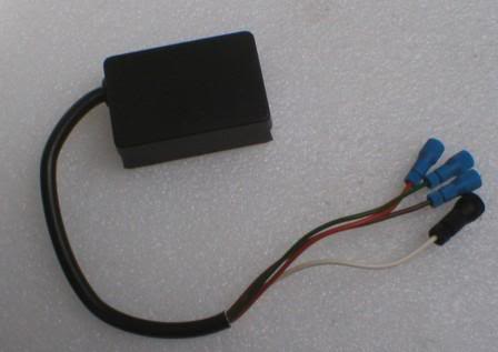
Image

It shows the Posi-taps fitted (by me to save time). This was a mistake, see later.


My first task was to remove my temporary diodes:

Image

I then looked at how the unit could be mounted. I found that next to the Double Injection Relay in the ECU box there was a spare clip where another relay could mount. This was perfect. Using the supplied adhesive pad, I mounted the clip onto the back of the unit.

Image

The next job was to “tee” into the loom with the Posi-Taps. The teeing job must be carried out before fitting the wires from the unit.

Image

The unit is fitted next:

Image

Now terminate the Posi-Taps. It is necessary to strip 6mm of insulation and splay out the strands so they slip over the “probe” in the end of the Posi-tap:

Image

Job finished and tidied up with a couple of Ty-Raps for neatness.
The Black you can see on a couple of wires is a little tape to insulate where the temporary diodes were formerly soldered.

Image

All in all, a very neat and easy-to-fit solution. I was very pleased at how the unit itself could slip into the ECU box and look almost OEM! I’m happy with the Posi-Taps and consider they’re a vast improvement over Scotch-Loks. They pierce the loom cable with a small pin. Full details of them here:

http://www.posi-lock.com

I have absolutely no connection whatsoever with E-Crofting but do recommend this kit to anyone who does not want to wield a soldering iron around their loom and need a ready-made solution.
Jim

Runner, cyclist, time triallist, duathlete, Citroen AX fan and the CCC Citroenian 'From A to Z' Columnist...
User avatar
AndersDK
Posts: 6060
Joined: 21 Feb 2003, 04:56
Location: Denmark
My Cars:
x 1

Post by AndersDK »

Thats a pretty amasing little posi-tap there.

I just hate their website demo video though :roll:
It takes for ever getting to the point, and you loose patience and start clicking the mouse : come on whats the big idea :lol:
And how is the main part actually tapped in to the existing wire ?
It looks like you will have to cut the tapped wire then insert this through a hole in the body of the posi-tap. Or is it simply a cut out in the threaded part - or what ? Really bad point on the demo there.
The demo is certainly NOT made for the end users, but made by and for the armani suit people signing contracts, not knowing how to use the product anyway :roll:

Explanations Jim :lol:

It seems though that I've bought my last supply of crimp connectors now 8)
Anders (DK) - '90 BX16Image
User avatar
CitroJim
A very naughty boy
Posts: 49658
Joined: 30 Apr 2005, 23:33
Location: Paggers
My Cars: Bluebell the AX, Polly the C3 Picasso, Pix the Nissan Pixo, Propel the duathlon bike, TCR Pro the road bike and Fuji the TT bike...
x 6204
Contact:

Post by CitroJim »

AndersDK wrote:Thats a pretty amasing little posi-tap there.

how is the main part actually tapped in to the existing wire ?
It looks like you will have to cut the tapped wire then insert this through a hole in the body of the posi-tap. Or is it simply a cut out in the threaded part - or what ?

Explanations Jim :lol:

It seems though that I've bought my last supply of crimp connectors now 8)
I confess I've not looked at the demo :oops:

This is how they work..

As you quite rightly deduced Anders, There is a cut-out in the threaded part which slips over the wire you wish to tap into.

In the body there is a needle-sharp pin and as you screw the body onto the threaded part the pin pierces the wire and makes contact with the conductor.

At the other end of the body there is what looks like a blunt bullet. To terminate the wire into it, you thread on the threaded top piece and strip back around 6mm of insulation and then splay (fan) out the individual strands of the conductor, place them over the bullet and screw up the top piece. They will not work for cables with solid conductors.

I like them as they seem to do less damage to the integrity of the tapped cable than a Scotch-Lok. I've seen cables almost severed by the Scotch-Lok blade. They are infinitely re-usable and I can see an application where you could use them to tap into a wire for test purposes and not do any great harm in the process.

They should be good for towbar wiring and radio wiring but I'd not like to use them where very heavy currents are involved such as auxillary driving lights.

I'll take some photos of a Posi-Tap dismantled and post them up in a bit.
Last edited by CitroJim on 20 May 2007, 17:52, edited 1 time in total.
Jim

Runner, cyclist, time triallist, duathlete, Citroen AX fan and the CCC Citroenian 'From A to Z' Columnist...
User avatar
CitroJim
A very naughty boy
Posts: 49658
Joined: 30 Apr 2005, 23:33
Location: Paggers
My Cars: Bluebell the AX, Polly the C3 Picasso, Pix the Nissan Pixo, Propel the duathlon bike, TCR Pro the road bike and Fuji the TT bike...
x 6204
Contact:

Post by CitroJim »

Here are some photos of the Posi-Tap.

This is the "Sharp End". The end that taps into an existing wire..

Image

This is the other end, where the new wire terminates. You can see what I call the "bullet" where the splayed ends of the conductor strands go. All is then held tight by the end cap.

Image

I elevated the body in this shot to make the "bullet" a little clearer.
Jim

Runner, cyclist, time triallist, duathlete, Citroen AX fan and the CCC Citroenian 'From A to Z' Columnist...
User avatar
AndersDK
Posts: 6060
Joined: 21 Feb 2003, 04:56
Location: Denmark
My Cars:
x 1

Post by AndersDK »

Great help Jim -

Thanx. All is revealed now 8)
Try that demo video - it really is silly, even a disaster :lol:

To stay on topic : looking forward to driving experience reports on the hyd repair kit fitted.
Anders (DK) - '90 BX16Image
User avatar
CitroJim
A very naughty boy
Posts: 49658
Joined: 30 Apr 2005, 23:33
Location: Paggers
My Cars: Bluebell the AX, Polly the C3 Picasso, Pix the Nissan Pixo, Propel the duathlon bike, TCR Pro the road bike and Fuji the TT bike...
x 6204
Contact:

Post by CitroJim »

AndersDK wrote:looking forward to driving experience reports on the hyd repair kit fitted.
It is a bit difficult to give a true experience in my case as I've only properly driven my Activa this morning along my normal journey to work and that is after fitting the kit, fitting the new ram bush, depressurising the hydraulics and consequent citarobics, a service and finally having driven the 205GTi more then the Activa recently.

It feels really lovely but that may well be more to do with finally curing the rear-end rattle. It is staggering how getting rid of an irritating noise really affects your perception of how a car feels.

Next week it'll get plenty of testing. I'm on leave and the girls are on half-term. Several trips to tourist attractions around the country will be undertaken.
Jim

Runner, cyclist, time triallist, duathlete, Citroen AX fan and the CCC Citroenian 'From A to Z' Columnist...
Post Reply