
That blanked port on the underside of the thermostat housing looks just right for a feed to the oil cooler, with the other end of the cooler going to the pump input. That way, there will only be flow through the oil cooler when the 'stat opens, which is correct. Much larger flow towards the radiator will happen at the same time.
Alternators don't provide good output when run too slowly. An idle speed of 800rpm needs a 3:1 pulley ratio for the alternator to be doing 2400rpm. An engine speed of 2000rpm (peak torque for the XUD) would give 6000rpm at the alternator, so full output for it too. (I once had an alternator output issue on a V8 Rover, which could be driven at very lazy engine rpm, which didn't suit the alternator at all. A Lucas depot fitted the alternator with a slightly smaller pulley, which solved the problem instantly, and got the ammeter (!) reading decent charge at urban road speeds.)
My Engine
-
XUD Marine
- Posts: 54
- Joined: 30 Jun 2019, 10:14
- x 8
Re: My Engine
I had not been to the boat since last Saturday, though had done a little homework. I went today and didn't do an awful lot, but did make a bit of progress.
I took some measurements of the throttle lever on the fuel pump and the cable travel. From that I calculated that I need to extend the lever by 20.8mm for its travel to match the cable from the Morse. If I do extend it, I will probably go a little more than that, to have some room for adjustment, as there is scope in altering the anti-stall at the engine end and there are stopper adjustment screws on the Morse end.
The conclusion I came to was there is a 2.5:1 ratio from the engine to alternator.
With this in mind, I had a play with the tacho dial settings, but still no luck in calibrating it.
I also managed to get heat going though my heater pipes, without (permanently) altering the hose layout. I put the mole grips on the hose after the T on the cooler side. This did not seem to have much effect to start with, I had tried this previously holding it by hand, but my hand got tired/hot before too long. But giving the engine a bit of rev for a while, I think created enough pressure from the water pump to force a proper bleed through the problem pipes.
Purged of air, the hot water seemed to flow after the grips were removed. This inspired me to jury rig the wiring to the heater fans. They will have a speed knob, but that will have to wait until I panel out the inside of the cabin bulkhead. For now I just bodged in an on/off rocker switch, to see how much heat it kick out. It was not that much, as the engine cooled surprisingly quickly while I was messing with wires, and it also takes a while to get up to a high temperature, so I did not really give it enough time for a proper test. The raw water cooling must be quite effective. There is no real discernible heat in the exhaust manifold with its water jacket, easily safe to touch with a bare hand.
I'll give the heater another try when I next give it a good run. It may be a welcome luxury in the winter months.
As for the piping, I may still adjust it as discussed. If I extend the throttle lever, I will need to move one of the cooler pipes, that means draining it. If I replace the fast-idle, that means draining it. So if I'm going to drain it, I may as well do everything that can be done while it's drained, which can include re-routing the cooler in pipe from the heater T to the stat, and replacing the T with an elbow.
The heater circuit should work better if the stat holds water back from the cooler during warm up.
I took some measurements of the throttle lever on the fuel pump and the cable travel. From that I calculated that I need to extend the lever by 20.8mm for its travel to match the cable from the Morse. If I do extend it, I will probably go a little more than that, to have some room for adjustment, as there is scope in altering the anti-stall at the engine end and there are stopper adjustment screws on the Morse end.
I have not been brave enough to try this yet. But if I extend the lever, it would make sense to do it while it's off.moizeau wrote: 14 Dec 2020, 19:54 When you take the top cover off the pump make sure you hold the spline in place whilst you lift, jiggle the cover...there are springs and things inside that you don't want to dislodge. Also mark the lever and spline so they go back in the same position.
The next job was to put a shiny sticker on an alternator fin, so I could measure its speed and compare it to the engine.white exec wrote: 14 Dec 2020, 21:46 Alternators don't provide good output when run too slowly. An idle speed of 800rpm needs a 3:1 pulley ratio for the alternator to be doing 2400rpm. An engine speed of 2000rpm (peak torque for the XUD) would give 6000rpm at the alternator, so full output for it too.
The conclusion I came to was there is a 2.5:1 ratio from the engine to alternator.
With this in mind, I had a play with the tacho dial settings, but still no luck in calibrating it.
I also managed to get heat going though my heater pipes, without (permanently) altering the hose layout. I put the mole grips on the hose after the T on the cooler side. This did not seem to have much effect to start with, I had tried this previously holding it by hand, but my hand got tired/hot before too long. But giving the engine a bit of rev for a while, I think created enough pressure from the water pump to force a proper bleed through the problem pipes.
Purged of air, the hot water seemed to flow after the grips were removed. This inspired me to jury rig the wiring to the heater fans. They will have a speed knob, but that will have to wait until I panel out the inside of the cabin bulkhead. For now I just bodged in an on/off rocker switch, to see how much heat it kick out. It was not that much, as the engine cooled surprisingly quickly while I was messing with wires, and it also takes a while to get up to a high temperature, so I did not really give it enough time for a proper test. The raw water cooling must be quite effective. There is no real discernible heat in the exhaust manifold with its water jacket, easily safe to touch with a bare hand.
I'll give the heater another try when I next give it a good run. It may be a welcome luxury in the winter months.
As for the piping, I may still adjust it as discussed. If I extend the throttle lever, I will need to move one of the cooler pipes, that means draining it. If I replace the fast-idle, that means draining it. So if I'm going to drain it, I may as well do everything that can be done while it's drained, which can include re-routing the cooler in pipe from the heater T to the stat, and replacing the T with an elbow.
The heater circuit should work better if the stat holds water back from the cooler during warm up.
-
white exec

- Posts: 7445
- Joined: 21 Dec 2015, 12:46
- x 1750
Re: My Engine
Some good progress there on several fronts!
These diesel engines are incredibly frugal on fuel consumption, and especially at idle and under very light load, so little fuel = little heat. The role of the thermostat is crucial, in completely blocking off any flow towards the radiator (your cooler). Before the 'stat opens, any heat should be heading towards the heater matrix. (Worth insulating those long heater pipe runs - but I think you said you'd done that already.)
Doing short warm-up tests is a bit difficult with these engines. On our 2.5TD, after refilling/working on the cooling system, simply getting it up to full working temperature, i.e. fans cutting in a couple of times, can take 30-40 minutes at idle. It is necessary to do this in order to bleed the system thoroughly.
On the alternator, just fit an alternator pulley 1/3 the diameter of the crankshaft one, and job will be done.
A warm cabin sounds a nice idea for Christmas...
Chris
-
XUD Marine
- Posts: 54
- Joined: 30 Jun 2019, 10:14
- x 8
Re: My Engine
I gave it another run yesterday afternoon, just to try the heater again. Though it did not do much more than tick over while I did a bit of woodwork. The temp didn't really get over 70.
Lagging the pipes is something I definitely need to do. They seem warmer near the engine, I would expect a bit of heat loss over the distance. I picked up some stuff today. I got both the foam tube stuff, and some silver spiral wrap.
The heater wasn't exactly cooking hot with the engine at 70. But I think with the pipes rearranged so it's not sharing hot water with the oil cooler, some lagging on the pipe and the engine doing some actual work, it should be better.
Another curious thing with the cooling system, the header tank did feel quite warm/hot, though the "radiator" pipe from the stat to it, was barely warm (the stat would not be open at 70degC) and the down pipe from the tank to the water pump inlet was notably cool. I guess the heat I could feel on the tank was just steam coming through the expansion pipe.
I also had another go with the tacho settings, but no luck. It did occur (now knowing the engine/alternator ratio) to me later, that when I first tried it on the setting of 6 (half 12 poles), as per the instructions, it may well have been showing the correct alternator speed. It did read around 2.5k, which seems reasonable for a 1:2.5 ratio. I may have to check that. But you would think from that, it would be easy to calculate the engine speed from that, based on the ratio. But the obvious figures did not work. 6 / 2.5 = 2.4, I tried multiplying, in case it works that way, 6 * 2.5 = 15. That does seem more logical, as I think the tacho's ratio setting is a division factor.
Assuming the alternator gives 6 pulses per its own rev, dividing pulses by 6 gives you 1 rev.
So at 1000 RPM engine speed, the alternator is doing 2500 RPM, with 15,000 pulses per min. Dividing 15,000 by 15 (6*2.5) gives you the 1000 engine speed.
Though setting to 15 does not seem to work, so I may have to think again.
I may try an experiment with the TDC sensor. I see it has 3 wires. Would I be right to assume they are positive, negative and signal? I don't have it to hand just now, but looking at photos, where it's not clear, the wires look red/brown, black and white/grey.
From the previous discussion about it, will the sensor work on either a notch or a peg, in a ferrous (magnetic) metal?
A likely spot seems the Jabsco pump drive mount, on the front of the crank shaft. It could be mounted on the pump's mounting tag, then something stuck on or screwed into to rotating drive mount.
That should be a simple 1:1 ratio with the engine.
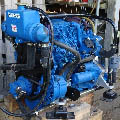
- Engine front, showing Jabsco raw water pump mounted on the front crank shaft pulley. Aslo alternator pulley, relative size.
-
XUD Marine
- Posts: 54
- Joined: 30 Jun 2019, 10:14
- x 8
Re: My Engine
I've been experimenting with the TDC sensor, as a back-up plan for the tacho. But I've not got it to work. It wasn't using the engine, just an old battery, a spare tacho and a drill for rotary motion.
I'm not sure I had it wired up right, as I just had to take a guess at how to do it.
The wire from the sensor went to a brown plug with 3 connectors. The three wires from the outer grey insulation had red, white and black individual insulation. Though after snipping off the plug and stripping some wire, the one with black, only had a very short bit of its own black insulation going into the plug, the rest is bare within the grey outer insulation.
I tried it with the red to the battery +, the white to the tacho sensor input, and black/bare to the battery -.
The drill was mounted in a vice with an allen key in the chuck, so the bent end gave an eccentric ferrous rotating target. I placed the sensor approx 1mm from the arc of the key end.
The result was, the needle did not even wiggle.
It could be it doesn't work, or I just set it up totally wrong.
Does anyone know how to properly wire it or set it up?
I couldn't make much sense of it from the diagrams in the manual. I only found it on two. On the BX Turbo, it appears to have two wires to the tacho. On the C15 it goes only to the diagnostic socket.
Here is the plug I snipped off. The marking on it, left to right: a "2" on its side, underlined. "AMP" is written under where the black/bare wire goes. "2" in the middle where the white wire goes. And "1" on the right where the red wire goes.
On another subject, a parcel arrived today with some parts. A new fast-idle control and thermostat. So I will now want to drain the system, then can remove the housing and it's old parts. While it's off, drill and tap hole in it to fit a tail for the pipe to the oil cooler. Then I can remove the T from the heater port. Then the heater is fed exclusively from its own port and the cooler from the thermostat housing cover. I can also move the return pipe from the oil cooler, so it does not get in the way of extending the throttle lever.
I'm not sure I had it wired up right, as I just had to take a guess at how to do it.
The wire from the sensor went to a brown plug with 3 connectors. The three wires from the outer grey insulation had red, white and black individual insulation. Though after snipping off the plug and stripping some wire, the one with black, only had a very short bit of its own black insulation going into the plug, the rest is bare within the grey outer insulation.
I tried it with the red to the battery +, the white to the tacho sensor input, and black/bare to the battery -.
The drill was mounted in a vice with an allen key in the chuck, so the bent end gave an eccentric ferrous rotating target. I placed the sensor approx 1mm from the arc of the key end.
The result was, the needle did not even wiggle.
It could be it doesn't work, or I just set it up totally wrong.
Does anyone know how to properly wire it or set it up?
I couldn't make much sense of it from the diagrams in the manual. I only found it on two. On the BX Turbo, it appears to have two wires to the tacho. On the C15 it goes only to the diagnostic socket.
- TDC Sensor Plug
On another subject, a parcel arrived today with some parts. A new fast-idle control and thermostat. So I will now want to drain the system, then can remove the housing and it's old parts. While it's off, drill and tap hole in it to fit a tail for the pipe to the oil cooler. Then I can remove the T from the heater port. Then the heater is fed exclusively from its own port and the cooler from the thermostat housing cover. I can also move the return pipe from the oil cooler, so it does not get in the way of extending the throttle lever.
-
white exec
- Posts: 7445
- Joined: 21 Dec 2015, 12:46
- x 1750
Re: My Engine
Just seen your two posts...
From the photo, the pulley ratio (crank:alternator) is 2.8:1.
It's most important that the thermostat is placed so that it blocks ALL flow towards your heat exchanger (which is capable of dissipating lots of heat, I'd guess), and obliges flow from the block/head to travel solely towards the heater matrix. This will allow both block and matrix to get up to working temperature quickly, and be maintained at the temp marked on the 'stat. You should go for an 88C or 92C 'stat. 90C is a good operating temp for these engines, and the heater matrix will be decently toasty at this figure too.
The usual diesel (flywheel) sensors 3 wires are
- red (or another colour)
- black
- screening
On the XUD here (with a new sensor), the screening runs from the sensor as far as its brown connector, but from there on only the other two connections lead off to the dash tacho.
It does, I think, matter which way round these two are connected, so that the pulses produces have the correct polarity.
The d.c. resistance of a working sensor of this type is approx 71 ohm.
Connecting it to the instrument the wrong way round shouldn't cause damage (although you might get no reading), but don't run a battery voltage into the sensor/tacho sensor input.
Chris
-
XUD Marine
- Posts: 54
- Joined: 30 Jun 2019, 10:14
- x 8
Re: My Engine
The 2.5 figure comes from readings on the hand-held digital tacho.
Crank shaft @ 790 = 2000 @ alternator, (2.531)
Crank shaft @ 880 = 2250 @ alternator, (2.557)
Crank shaft @ 1060 = 2700 @ alternator, (2.547)
Which seems reasonably consistent at just above 2.5, so I rounded to 2.5
Today I tried switching the red and white wires, but still nothing to show. There are sensors available, if the sensor is duff, or the tacho doesn't like it.white exec wrote: 30 Dec 2020, 18:16 Connecting it to the instrument the wrong way round shouldn't cause damage (although you might get no reading), but don't run a battery voltage into the sensor/tacho sensor input.
But I have not yet given up on the alternator feed, which is the preferred option (the TDC sensor is the fall-back plan) as everything has been wired in place for it. Theoretically, it should just work, with the right ratio setting. But I just find it hard to believe how hard that is to find, it should just be simple maths.
I have come up with some other numbers to try, including those based on your 2.8 ratio.
I was going to test today, an excuse to fire it up and create some warmth, but that won't be happening for a while. The hose that feeds my raw water was frozen solid, so no go due to that.
Instead I drained coolant and removed the stat housing cover, in preparation for the new parts and drilling for the hose fitting.
It turns out that blank port on the bottom is just the right place. It wasn't clear with the cover on which side of the thermostat it was on (looking border-line). But I see now it's on the radiator port side, so feeding the cooler there, I won't be cooling the oil until the engine is hot.
The heat exchanger/header-tank was already fed form the radiator port, it's just now the oil cooler feed will join it on that side of the stat. Yes, I assume the heat exchanger will be more efficient at cooling than a car's air-cooled radiator, so the thermostat is a must.white exec wrote: 30 Dec 2020, 18:16 It's most important that the thermostat is placed so that it blocks ALL flow towards your heat exchanger (which is capable of dissipating lots of heat, I'd guess), and obliges flow from the block/head to travel solely towards the heater matrix. This will allow both block and matrix to get up to working temperature quickly, and be maintained at the temp marked on the 'stat.
With a non-committed attempt this afternoon, that fast-idle sensor seems like it's going to be a tough one to unscrew, I may tackle it properly tomorrow.
-
white exec
- Posts: 7445
- Joined: 21 Dec 2015, 12:46
- x 1750
Re: My Engine
My apologies - you are quite right on the pulley ratio: measuring the photo again gives 2.54:1, so agree with yours.
Possible that your rotation sensor and the tacho aren't electrically matched, as you say.
Throw some antifreeze into the bucket?
Possible that your rotation sensor and the tacho aren't electrically matched, as you say.
Throw some antifreeze into the bucket?
Chris
-
XUD Marine
- Posts: 54
- Joined: 30 Jun 2019, 10:14
- x 8
Re: My Engine
It was the hose from the tap, across the yard, that feeds the bucket, that was frozen. But I have committed now, having drained the coolant and removed the stat cover. I won't be running it until the cooling system is rearranged. Oddly, the bucket does now contain antifreeze, because I drained the engine into it (after smashing the ice and emptying it). Though a lot ended up in the bilge sump. I don't have space for a container under the drain hole, and being flush with the block, it was hard to force it into a bit of pipe to lead to the bucket. It could do with a little spout.
Anyway, I've had a bit of a go at the stat cover this morning. The fast-idle did come out, with help from a vice and extra large adjustable. It was missing the copper washer, I think someone put silicone in there to seal it, which didn't make it easy to move.
The bit I'm stuck with now is the cir-clip holding the stat. It absolutely will not move at all. I've tried hitting it with a punch and hammer, no movement at all. Maybe picking out the rubber seal will help, or bathing it in something. It seems very well fused in there.
-
white exec
- Posts: 7445
- Joined: 21 Dec 2015, 12:46
- x 1750
Re: My Engine
Soak that circlip in PlusGas, overnight if possible. IIRC it's a steel clip in an alu slot, so ripe for a bit of surface corrosion.
Buff the clip surfaces clean before refitting.
What temp is the new 'stat, just out of interest?
Buff the clip surfaces clean before refitting.
What temp is the new 'stat, just out of interest?
Chris
-
moizeau

- Donor 2024
- Posts: 1855
- Joined: 12 Jan 2015, 16:08
- x 427
Re: My Engine
If you haven't got any plusgas a 50/50 mix of atf and acetone works very well.
Pete
Notice the BX is still top the list but sadly gone
Notice the BX is still top the list but sadly gone
-
XUD Marine
- Posts: 54
- Joined: 30 Jun 2019, 10:14
- x 8
Re: My Engine
I did manage to get the circlip out, via bruit force and determination. The pliers were not really up to the job, I could only just reach from hole to hole, then I could squeeze so far, then they slip out. I did manage to get just enough squeeze to stick a blade between it and the retaining lip, then prise it out bit by bit with a flat screwdriver working around. Though I did break off a small bit of the lip in the process, but probably not enough to be a problem, though I will have to file the face flat to seal with the gasket. I just foresee it being hard work to put back in, it seems quite a strong clip.
The new stat I got said it was 81, bought before you recommended a higher temp. But I gave both the old and new a kitchen test (pan of water with thermometer), once I got it out. The old one opened first, around 80/low 80s. The new one opened in the high 80s. Cooling down, the new one closed sooner (warmer), the old one closing later as I add more cold water to the pan. In fact it does not seem to fully close. With it dry, at room temp now, there is a slight gap. Though the new one has a breather hole that the old one lacks.
By that, it should be an improvement on the old one, though the main reason for removing it was to make the new hole, I wasn't sure if I needed a new one, but I would not have got it out without destroying the rubber seal, which the new came with.
I just need the hose-tail now. I'm hoping the place that sells them in town is open tomorrow morning. I think a 3/8 BSP should be about right for the 16mm hose.
-
white exec
- Posts: 7445
- Joined: 21 Dec 2015, 12:46
- x 1750
Re: My Engine
I would delinitely recommend getting hold of a higher rated thermostat - eg 88C - even if it means a bit of delay in getting things going again. 81C is a very chilly thermostat, likely to give annoyingly cool running in a car, and maybe even more so on your generously cooled marine application. Avoid 82/84 types as well.
Chris
-
XUD Marine
- Posts: 54
- Joined: 30 Jun 2019, 10:14
- x 8
Re: My Engine
Hello, it's been a while. But I have not been doing too much engine related stuff lately. I had been concentrating on fitting out the cabin as the *final* job. Though I did finally get around to fixing that fuel leak by replacing the O rings on the throttle spindle.
On the 1st of October I had a trial launch on an inland lake to check every thing was OK. Most issues were related to the trailer, which is another job. Here are some photos.
Thank you to all who helped here to get me this far on the project.
It seemed to run OK. I was a little dissapointed with the speed, I only managed to get a max of 12 knots, but I guess that's enough. It only revved to about 3k when working under load. Also surprised how much quieter the engine sounds out in the open, as opposed to in the shed where it seemed horribly noisy, even with 20mm of insulation inside the engine box.
There was just one issue with the engine I noticed when I examined it after a good blast around the lake. It had developed a leak at the Diesel heater, by the water pump. As found the heater had just two stubs of pipe coming out the top. I fixed the line from the tank to the inward one and the out one I fixed a pipe to the primer bulb, that goes on to the filter.
I had noticed before the launch one of the pipe stubs had a wobble, but there was no leakage at the time, so I didn't worry too much.
I'm just curious how the pipes are fixed in there, as it's not obvious to me, and wonderd if I could re-fit new pipes to it.
On the other hand I could easily bypass it by putting the line from the tank straight to the primer bulb, but I suppose it will run a lot nicer with some warmth to the fuel.
Or is there a good alternative I could use? Such as an electric in-line heater.
Any advice?
On the 1st of October I had a trial launch on an inland lake to check every thing was OK. Most issues were related to the trailer, which is another job. Here are some photos.
- In motion
It seemed to run OK. I was a little dissapointed with the speed, I only managed to get a max of 12 knots, but I guess that's enough. It only revved to about 3k when working under load. Also surprised how much quieter the engine sounds out in the open, as opposed to in the shed where it seemed horribly noisy, even with 20mm of insulation inside the engine box.
There was just one issue with the engine I noticed when I examined it after a good blast around the lake. It had developed a leak at the Diesel heater, by the water pump. As found the heater had just two stubs of pipe coming out the top. I fixed the line from the tank to the inward one and the out one I fixed a pipe to the primer bulb, that goes on to the filter.
- Fuel heater
I'm just curious how the pipes are fixed in there, as it's not obvious to me, and wonderd if I could re-fit new pipes to it.
On the other hand I could easily bypass it by putting the line from the tank straight to the primer bulb, but I suppose it will run a lot nicer with some warmth to the fuel.
Or is there a good alternative I could use? Such as an electric in-line heater.
Any advice?
-
moizeau
- Donor 2024
- Posts: 1855
- Joined: 12 Jan 2015, 16:08
- x 427