My Engine

This is the place for posts that don't fit into any other category.

Moderator: RichardW

Post Reply
User avatar
XUD Marine
Posts: 54
Joined: 30 Jun 2019, 10:14
Location: North Lincs
My Cars: XUD7 1.8 Marine Engine
x 8

Re: My Engine

Post by XUD Marine »

It's been a while since I gave an update, but things have slowed down a bit, so not much to report.
I got the new thermistor, but it turned out on testing that did not match the gauge, so ended up getting another sensor/gauge pair. At least they were not expensive.
Anyway the progress this weekend, the engine beds are nearly ready, a job I had been putting off.
IMG_20191222_162827_BURST1577032107712.jpg
IMG_20191222_162855_BURST1577032135771.jpg
I ended up using some 4x4 fence posts. They may not look like much, but they took some fitting. The space for the original engine was off-set form the centre, so the bilge floor there is asymetrical, the angle of slope inward varies along the length, the starboard side the bearer is sat on ribs, but the port is not. But I needed to get the main bearers level and even, so that involved a lot of measuring, marking, sawing and chiseling until they were level at even heights.
The engine footprint is only 2 foot long, but I made the bearers 5 foot to spread the weight on the hull. They are stuck down now with just expanding foam, which holds them in place and fills any discrepancies in my fitting.
The wedges, which are 3 foot long, are not yet fastened, though the two parts are glued together. My idea is to leave them loose, then try sitting the engine on them, then I can move them back or forward, and the engine up and down them to find the right height level to bring the gearbox flange in-line with the prop shaft flange (seen at the back) with the angle remaining a constant.
I can fine tune the angle and height with the nuts on the rubberised mounting feet, but want it somewhere close to begin with.
feet01.jpg
Once I know were the wedges will sit, where the feet sit on the wedges and where the front of the engine will be, I will move the engine off out the way, then trim off the front of the wedges, fasten the wedges to the bearers, fit a bulkhead in front of the engine (I may leave a removable, but watertight service hatch in that) and fibre-glass over the lot to seal and fasten it to the hull. After a lick of paint, it will be ready to sit the engine on and fasten down the feet.
I may put a mini bulkhead of a couple of inches between the bearers at the back, just to comply with the "Boat Safety Scheme" which says you should have a tray or separate bilge compartment under the whole engine and gearbox, to contain any oil leakage, separate from the general bilge water which is pumped overboard.

I managed to get hold of a Morse controler at a good price, so that's another component found. It's a single lever for gear shift and throttle. These oftern come with a Neutral Safety Switch which prevents starting when in gear. The manual said it was an optional extra, and opening it up, mine didn't include one. Looking them up on-line, chandlers are asking about £45 for these. It's just a micro switch that sits under a cam on the gear shift mechanism that your starter circuit goes through.
Looking on Ebay, I found waterproof micro switches for £4.50. So it's official, you label something "marine" and can add an extra zero to the price tag. I don't need a high amp rating, becuase I will be firing the starer solonoid through a relay.
Off on that tangent, while I've not been doing that much hands on lately, I have been planning the electrical sysem further and have some questions about current draw for various things, for choosing suitable cables to the engine.
Where I can I would like to keep things tidy and minimal, using multi-core signal wires where I can. But I don't want to skimp on cable weight where it matters. Obviously, starter circuts, glow plugs, etc, heavy duty stuff, I know. But what about the stop solonoid, how much current does that draw, would I get away with a tiny signal wire, or does it need something more?
I think things like oil/temp warnings will be OK on signals, that's just a little light (maybe LED) and switch. What about gauges to sensors? I wouldn't think they would need much cable weight, or will volt drop over distance affect resistance and give false readings? The gauge/sensor that is different is the alt W to tacho, as it's not simply a resisitor in the circuit, but outputting a signal, I can't imagine the tacho draws much, but I'm cautious about alterantors, as I don't fully understand them. Is that safe on a little siganl wire?
User avatar
white exec
Moderating Team
Posts: 7445
Joined: 21 Dec 2015, 12:46
Location: Sayalonga, Malaga, Spain
My Cars: 1996 XM 2.5TD Exclusive hatch RHD
1992 BX19D Millesime hatch LHD
previously 1989 BX19RD, 1998 ZX 1.9D auto, 2001 Xantia 1.8i auto
and lots of Rovers before that: 1935 Ten, 1947 Sixteen, 1960 P5 3-litre, 1966 P6 2000, 1972 P6 2000TC, and 1975 P6B 3500S
x 1752

Re: My Engine

Post by white exec »

XUD Marine wrote: 22 Dec 2019, 20:46 Off on that tangent, while I've not been doing that much hands on lately, I have been planning the electrical sysem further and have some questions about current draw for various things, for choosing suitable cables to the engine.
Where I can I would like to keep things tidy and minimal, using multi-core signal wires where I can. But I don't want to skimp on cable weight where it matters. Obviously, starter circuts, glow plugs, etc, heavy duty stuff, I know. But what about the stop solonoid, how much current does that draw, would I get away with a tiny signal wire, or does it need something more?
I think things like oil/temp warnings will be OK on signals, that's just a little light (maybe LED) and switch. What about gauges to sensors? I wouldn't think they would need much cable weight, or will volt drop over distance affect resistance and give false readings? The gauge/sensor that is different is the alt W to tacho, as it's not simply a resisitor in the circuit, but outputting a signal, I can't imagine the tacho draws much, but I'm cautious about alterantors, as I don't fully understand them. Is that safe on a little siganl wire?
Just been wondering how our Blue Smurf power unit was doing. One of the more interesting posts here!!

Re: cabling...

Starter solenoid itself can mop up as much as 25A, so you are right to use a relay to operate it.
25A - use 2.5mm² stranded cable.

Glow plugs (while on the subject of high current) - use 6mm² cable to and from the GP relay, and solder the eye connectors, not just crimp.

Instruments, sensors, gauges - 0.5 or 1mm² quite adequate.

Alternator - main output cable, 25mm² (70-90A capable), 16mm² (54-72A) if quite short.
Other connections to alternator (perm +12v, IGN sw +12v, warning light) - 1 or 1.5mm².
W to tacho - You could use a screened cable for this, Gnd'ing the screen. Tiny current.

Hope helpful.
Chris
User avatar
Pug_XUD_KeenAmateur
(Donor 2018)
Posts: 1168
Joined: 22 Apr 2013, 17:24
Location: South Midlands / M4 / M5
My Cars: 405 naD Est
x 232

Re: My Engine

Post by Pug_XUD_KeenAmateur »

Sounds sensible, lets hope my probably inadequate Solenoid and GP cables hold for the purposes of engine testing, when I eventually get around to it
Puxa
GoceKU
Posts: 25
Joined: 06 May 2020, 13:47
Location: Kumanovo, Macedonia
My Cars: Peugeot 607 2,7 HDI 150Kw
Peugeot 405 SR
Peugeot 405 GLD
Peugeot 405 Mi16x4
Peugeot 405 RWD
Peugeot 605 SRdt
Peugeot 605 V6 3.0 auto
Peugeot 605 2.1td
Peugeot 605 Sri
Peugeot 206 1.4i
Renault R19
Ranault Megane Coupe
Renault clio
Lada Niva 1600
Fiat 600
x 2

Re: My Engine

Post by GoceKU »

I think i have the same engine, but a bit older, come out of a 1983 peugeot 305 and the title says it's a 1905cc 47 kw unit, what did happen did the owner get this one running ?
DSC_0002JPG.jpg.0d67ce22e1c35bb480125a54cb4245f9.jpg
User avatar
white exec
Moderating Team
Posts: 7445
Joined: 21 Dec 2015, 12:46
Location: Sayalonga, Malaga, Spain
My Cars: 1996 XM 2.5TD Exclusive hatch RHD
1992 BX19D Millesime hatch LHD
previously 1989 BX19RD, 1998 ZX 1.9D auto, 2001 Xantia 1.8i auto
and lots of Rovers before that: 1935 Ten, 1947 Sixteen, 1960 P5 3-litre, 1966 P6 2000, 1972 P6 2000TC, and 1975 P6B 3500S
x 1752

Re: My Engine

Post by white exec »

It all went quiet on the smurf-blue engine story. Wonder what happened?

That's an interesting cast lump on the top of the rocker cover in your photo.
The normal breather is on the oil-filler cap, so interesting to know what the other hose (and lump) is...
Chris
User avatar
XUD Marine
Posts: 54
Joined: 30 Jun 2019, 10:14
Location: North Lincs
My Cars: XUD7 1.8 Marine Engine
x 8

Re: My Engine

Post by XUD Marine »

Hello again, and sorry for the extended absence. Though I have been keeping busy, progress has been slow, and there hasn't been much to report on the engine side of things through the year, until now.
The next landmark, regarding the engine was Easter weekend, when I got it lifted into the boat. Once in position I did have to kick myself. The angle of the engine beds wasn't at all bad, but somehow, the level was way out. The engine was about an inch higher than it should, so the gearbox flange did not line up with the prop shaft flange. I can't think how I got it that wrong, it must have been a case of adding when I should have been subtracting to get that kind of margin of error.
This results in me having to move the lump backwards off the beds so I can go to work with a grinder, saw and chisel, to lose an inch and a quarter off the top of the beds. They are made from 4x4 fence posts, laminated with GRP, so not the easiest to cut down, but it had to be done.
Engine beds, freshly primed.
Here you see the engine in its place. Note the step at the front of the beds where it was cut down. But now the gearbox lines up perfectly with the prop shaft, and is coupled.
In the background is the woodwork I have been busy with. That white woodwork will be lockers for storage, seating, steps for boarding and conceal the cable runs. Under the white sheet, at the front left is the diesel tank. The battery locker is to the right of the engine, behind the three vent holes in the bulkhead.
Engine in situ.
Engine in situ.
At this point I would be eager to get it running. But there is a lot to do yet. I need fuel lines, feed and return, then all the bit around the engine, between the fuel warmer, primer bulb, filter and injection pump. I need a feed of cooling water. You can't run it dry, because the impeller will burn out. It also need to exhaust, to get all use used water out the boat. The other big job is the electrics, which was my next task.
I could have jury rigged the rudimentary electrics to get it going, but I went ahead and fitted the whole system (or as much as could be done a at this stage). That took quite a bit of work, creating the dashboard was a big job itself. And as usual, one job leads to another, as there is an order things have to be done. Fitting out the cabin was going to be a late priority, but because a lot of cables run on the inside of the cabin bulkhead, I had to build the wood structure inside there for the cable to pass through it. I also needed those white lockers in the mid section, as the conduits would run just under the locker tops. So there was quite a bit of woodwork and painting to do, to get the electrical systems in.
The electrics went surprisingly well, without any major hiccups, (against form).
The dashboard
The dashboard
Engine connected
Engine connected
Here are a few additions, the exhaust pipe, fuel pipes and primer, also there is now a T from the heater stem, feeding the oil cooler and cabin heater. Also note at the front, the wheel, I got the hydraulic steering fitted and working, the pump is mounted inside the bulkhead. Beside the wheel the Morse control lever. The two conduits down the right of the engine contain the hydraulic steering pipes and the engine control cables.
Fitting the fuel lines was not much fun. I stared out with copper pipe. When I stared to bleed through to the filter, I start to question just how much air can a length of pipe contain. Sat on the deck (I fitted the aft deck too) beside the engine, squeezing the bulb, I can hear a noise from the tank area. It must be drawing air in. I check and refit the fittings to the valve on the tank, it still makes a sound, drawing air. After a while I finally discover, it's a leak in the actual length of pipe where I could not see, not a faulty joint as I assume.
I end up removing the copper pipe and replace with rubber hose. That should be it. But with all the disturbance at the tank valve, the fitting to the tank has worked loose and the tank now leaks diesel into the bilge. Attepts to seal it fail. I end up syphoning out the tank, but the fitting still leaks. The fitting that was on it, wasn't really fit for purpose, so I empty it again, and buy a proper fitting. That did the trick. I can now bleed it as far as the injector pump. The engine gets its vital fluids, ATF for the gearbox, engine oil and coolant. I run a hose across the yard for the raw water, into a bucket, to be sucked into the sea-cock.
So it took as long as the 28th of November, just about two weeks ago, to finally fire it up.
It had to turn over a good few times, to bleed through to the injectors, but once it got there, it was quite happy to run.
This is of course a major breakthrough, and it seems to run well, but there are a few issues that need attention. For now, I think I have rambled long enough, so I will leave that until tomorrow.
User avatar
white exec
Moderating Team
Posts: 7445
Joined: 21 Dec 2015, 12:46
Location: Sayalonga, Malaga, Spain
My Cars: 1996 XM 2.5TD Exclusive hatch RHD
1992 BX19D Millesime hatch LHD
previously 1989 BX19RD, 1998 ZX 1.9D auto, 2001 Xantia 1.8i auto
and lots of Rovers before that: 1935 Ten, 1947 Sixteen, 1960 P5 3-litre, 1966 P6 2000, 1972 P6 2000TC, and 1975 P6B 3500S
x 1752

Re: My Engine

Post by white exec »

Really good to hear about our marine smurf again!
You've done a phenomenal amount of work there, mechanical, electrical and coachwork (coachwork??).
Great to know that the engine has finally fired up, and is managing to pump to/from your bucket!

Exciting stuff! Look forward to some more winter posts, as things progress.
Chris
User avatar
XUD Marine
Posts: 54
Joined: 30 Jun 2019, 10:14
Location: North Lincs
My Cars: XUD7 1.8 Marine Engine
x 8

Re: My Engine

Post by XUD Marine »

While it mostly seems good, there are a few issues to look at, mainly regarding the alternator and revs. When first started, I do need to give it a quick blast of revs for the alternator to kick in, and the battery light to go out, but I suppose that's not too unusual.
But what I noticed at first was the tachometer dial on the dash looked way too high, it was showing 2.5k RPM at tick-over. I did think it sounded maybe a tad fast by ear, but not that much, so maybe the tacho was not calibrated right.
It is calibrated by a scale factor which can be set. According to the instructions, when run from an alternator, the scale should be half the number of poles in the alternator. I believe it has 12, so that should make the tacho scale 6.
This did lead to me monkeying around with the idle speed and anti stall adjustments. I did get it ticking over quite slow, to the point it sounded a bit "agricultural", and the tacho was still reading well over 1k, so I concluded that the tacho was not correctly calibrated, even though it had been done according to the instructions.
The next step was to acquire one of those digital hand-held tachos, to see what speed the engine was actually doing, in order to set it ticking over the right speed, and to set up the the tacho dial properly.
After I got that, I played with the idle adjustment to get it ticking over at 800 RPM, as per the Haynes Manual.
But having done this, I still could not calibrate the tacho dial correctly. I could adjust it so it read 800 too, matching the digital tick-over speed, but when the revs are increased, the reading did not go up proportionally, so they only coincided at tick-over speed.
I'm not sure which is at fault, the alternator signal, or the tacho. Bear in mind, the alternator did not have a W terminal, I made one by soldering a wire inside. I also tried it with another tacho, one that is virtually the same, but with a range up to 4k instead of 6k. The results were pretty much the same, I could not get a calibration to match.
I don't know if there is a way of testing the output signal from the alternator.
This leads on to another related query. When I first connected the Morse control lever and its cable to the throttle, I did not have a lot of range of movement in the hand lever from idle to full-on. This would mean a very fine control would be needed to adjust engine speed, it would be nice to have the full range of movement offered by the Morse lever, but I'm constrained by the movement of the pump lever. I didn't suppose there was much I could do about this, except maybe extend the lever on the pump, but that isn't really practical.
I did find I got a bit more movement when adjusting the anti stall. The question is, can I alter that to get more movement, then compensate for it with the idle adjust? Of course I don't want the engine prone to stalling, but it would be good to have a range of speeds between tick-over and full-hole, easily obtainable, rather than too fine a line from one extreme to the other.
When playing with the two adjusters, I think I found a point at the low end of the anti stall, where nothing much changed, I could move the pump lever by hand a distance from the stop, before revs increased. But that is maybe down to the idle adjustment. I'm just wondering if this is a feasible way of increasing the range of movement in the lever, though movement that does not alter speed is somewhat redundant.
Now another one relating to the revs. When I set it up at 800 tick-over, the engine was warm. I noticed when I started it from cold another day, it sounded a bit slow and rough. A quick check with the digital tacho, and it was a bit slower than the 800 I set. Once it warmed up, it got up to speed and sounded normal. So I'm thinking the fast idle thermostat isn't working, as it should be faster to start with, until it warms up, not slower. The next time, with the engine cold, I measured the cable, and put a mark on it at the ferrule. Once it warmed up, I could see no movement in the cable, so I guess it doesn't work.
Just one more about the injector pump, I noticed a little bit of fuel weeping out on it, not a lot, but it's there. I appears to be coming from the lever pivot, the one on the main lever the cable goes to, not the little one linked at the top.
Another concern, the oil pressure is reading high, around 5 on tick-over, which seems high. Though I have since noticed it drop, once it warms up. It may be just the oil gets a bit thick in this cold weather.
One other thing bugging me, though not an immediate concern. I'm not getting anything through the heater pipe circuit.
All the coolant pipes around the engine get warm when the engine warms, but the pipes to the cabin heater don't.
Could it be the water is taking the path of least resistance, with the heater circuit being a relatively long round trip?
The heater port on the engine goes to a T split, one side goes to the oil cooler, the other to the heater. So maybe the water is just taking the shorter journey to the oil cooler and bypassing the round trip to the heater. Though I would think the vacuum from the pump inlet would draw it through, even if the pressure at the outlet did not.
The other theory is, I did not bleed that circuit properly. I did try, but I may have to try again.
User avatar
xantia_v6
Forum Admin Team
Posts: 9053
Joined: 09 Nov 2005, 22:03
Location: France or NewZealand
Lexia Available: Yes
My Cars: -
1997 Citroen Xantia V6 (France)
1999 Citroen XM V6 ES9 (France)
2011 Peugeot 308 CC THP 155 (NZ)
1975 Jaguar XJ-S pre-HE (NZ)
x 825

Re: My Engine

Post by xantia_v6 »

As I understand it, the tachometer calibration method is going to get the tachometer reading correct alternator RPM, which will be quite a difference from engine RPM. You need to take the pulley ratio into account.

Did the alternator have a warning light in its original application (I expect so), do you have one in your current configuration? If not, that could explain a high cut-in speed.
User avatar
white exec
Moderating Team
Posts: 7445
Joined: 21 Dec 2015, 12:46
Location: Sayalonga, Malaga, Spain
My Cars: 1996 XM 2.5TD Exclusive hatch RHD
1992 BX19D Millesime hatch LHD
previously 1989 BX19RD, 1998 ZX 1.9D auto, 2001 Xantia 1.8i auto
and lots of Rovers before that: 1935 Ten, 1947 Sixteen, 1960 P5 3-litre, 1966 P6 2000, 1972 P6 2000TC, and 1975 P6B 3500S
x 1752

Re: My Engine

Post by white exec »

You should set the engine idle (and sort the cold-start thermostat) first, so that the throttle lever on the pump is doing its stuff correctly. Disconnect and forget about the Morse control at this stage.

When that's done, turn attention to the Morse. The cable sweep at the Morse end must match the lever sweep at the pump end, obviously, so there are options:
- decrease the cable movement at the Morse end (move the cable connection point nearer the pivot)
- extend the pump lever, as you've said; ought not to be difficult.
- do a bit of both.
You must get the pump controls right first, and then sort the Morse action.

Cabin heater flow
Could be a bleeding issue, especially if the pipework from engine block to cabin matrix is long, or with any uphill or raised sections. Fit a bleeding screw at the matrix end, and one at any high-point on the pipe run.
To aid bleeding, use the "header bottle" technique (into the filler of the expansion tank) to help force air out of the system.
If you suspect there is an 'easy path' making like difficult for the flow through the matrix, try reducing that flow (eg use a hose crimper, or some moles) to see whether that helps. The oil cooler path may just need strangling a bit, or the T-connection altering.

Tacho
As Mike says, a working alternator warning light is essential for the alternator to start outputting and operate correctly. Many alternator (IGN, Charging) lights also have a resistor in parallel with the tungsten bulb (do not use an LED) to provide the necessary path in the rare event of the bulb blowing.

Revs check with hand-held optical tacho
I have just acquired one of these, and have been using it on the camshaft pulley on my XUD, which runs at exactly half of engine revs. Two white stickers at 180deg on the pulley should have given crankshaft revs, but the plated finish onthe pulley was enough to make the hand-held readings erratic. Sorted by using a black felt pen on the pulley, with the white stickers attached afterwards.

Oil pressure
What you describe sounds normal, with a pressure fall as things warm up, most noticeable at idle. So long as pressure is ok at 1500-2000rpm with a warmed-up engine, you should be fine. Presumably there is an oil pressure warning light and switch.
Chris
User avatar
XUD Marine
Posts: 54
Joined: 30 Jun 2019, 10:14
Location: North Lincs
My Cars: XUD7 1.8 Marine Engine
x 8

Re: My Engine

Post by XUD Marine »

xantia_v6 wrote: 13 Dec 2020, 00:49 As I understand it, the tachometer calibration method is going to get the tachometer reading correct alternator RPM, which will be quite a difference from engine RPM. You need to take the pulley ratio into account.

The alternator runs at half crankshaft speed, I assumed it would account for that, with the number being half the poles. Though I'm not certain how the signal works, is it one pulse per pole (12 per rev), or only the positive poles, which would half (6 per rev) the count?
The first thing I tried was altering the scale by factors of 2. So I tried 3, 12, 24. It's actually around 23/24 that it matches the 800RPM, but that's the only speed it matches on that setting.
Though I may need to perceiver with altering the setting, as it can be a bit difficult to get feedback. When I make a live adjustment, with the engine running, it does not always update the reading straight away. I have to rev it up and make the needle move, then it will settle back in a different place, so it's not the easiest to adjust.
Another option is to revisit the idea of using the original TDC sensor.
xantia_v6 wrote: 13 Dec 2020, 00:49 Did the alternator have a warning light in its original application (I expect so), do you have one in your current configuration? If not, that could explain a high cut-in speed.
I don't know exactly what the engine was in before, certainly a road vehicle (car/van), I believe it was a Peugeot, not Citroen, as it was named as being Peugeot. So I imagine it did have a battery light, and it does have one now. The light is seen in the previous image of the dashboard, illuminated in red, linked to the "ignition" position of the start key with a battery symbol.
I have used LEDs everywhere, with the exception of the battery light, which is an actual bulb.
white exec wrote: 13 Dec 2020, 08:05 You should set the engine idle (and sort the cold-start thermostat) first, so that the throttle lever on the pump is doing its stuff correctly. Disconnect and forget about the Morse control at this stage.
I was thinking, since I discovered that the cold start wasn't working, that should be fixed first, as it should alter the idle speed, when it actually moves the lever.
Are the thermostatic sensors easy to get hold of? Or maybe it just needs taking out and looking at, I know some parts of the coolant system can get a bit furred up.
white exec wrote: 13 Dec 2020, 08:05 When that's done, turn attention to the Morse. The cable sweep at the Morse end must match the lever sweep at the pump end, obviously, so there are options:
- decrease the cable movement at the Morse end (move the cable connection point nearer the pivot)
- extend the pump lever, as you've said; ought not to be difficult.
- do a bit of both.
You must get the pump controls right first, and then sort the Morse action.
Morse Control range
Morse Control range
Morse control linkages
There is not a lot of (any) scope for adjustment at the Morse end, you can only adjust the stops, to an extent. I would have to butcher the throttle arm by drilling another hole closer the pivot, but I'm relucatant to mess with it.
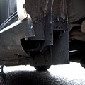
At the engine end, a longer lever would clash with the cooler pipe for the oil. But It may be that I will have to drain the coolant, and maybe rethink the pipe layout. Altering the engine end does seem the more viable option.
white exec wrote: 13 Dec 2020, 08:05 Cabin heater flow
Could be a bleeding issue, especially if the pipework from engine block to cabin matrix is long, or with any uphill or raised sections. Fit a bleeding screw at the matrix end, and one at any high-point on the pipe run.
To aid bleeding, use the "header bottle" technique (into the filler of the expansion tank) to help force air out of the system.
If you suspect there is an 'easy path' making like difficult for the flow through the matrix, try reducing that flow (eg use a hose crimper, or some moles) to see whether that helps. The oil cooler path may just need strangling a bit, or the T-connection altering.
I think it most likely is a bleeding issue, there is a bit of a high spot in both directions where the pipes pass through the cabin bulkhead. I't one of those things I did, then afterwards think, why did it do that. I think because to keep it on a level, I would have had to work behind the fuel tank, which was awkward, but a rise like that is going to be an air trap.
I'm wondering whether to alter the coolant pipes, to do away with the T, and make the hearer port dedicated to the heater, then feed to oil cooler some other way. The engine did not have an oil cooler originally, so there is no extra port for it in the thermostat housing. The digram for a BX in the manual shows the cooler fed from an extra port, then returning into a Y in the main return pipe. Could I hijak the main return pipe to go via the oil cooler, instead of directly back to the pump?
Coolant pipes
Coolant pipes
white exec wrote: 13 Dec 2020, 08:05 Tacho
As Mike says, a working alternator warning light is essential for the alternator to start outputting and operate correctly. Many alternator (IGN, Charging) lights also have a resistor in parallel with the tungsten bulb (do not use an LED) to provide the necessary path in the rare event of the bulb blowing.
The light is there, as you can see, but I never thought to add a resistor. One other point about the charge system. I have a twin battery system (I won't have a single battery on an open boat) this means the charge itself going through an accumulator gadget, then from that to the batteries. This lets me charge both batteries, while they are separate circuits. I'm not sure if that is affecting things. I can see the batteries are charging, as the volt meter goes from around 13, up to 14 when the engine runs. The toggle switch by the meter lets me view either battery.
white exec wrote: 13 Dec 2020, 08:05 Revs check with hand-held optical tacho
I have just acquired one of these, and have been using it on the camshaft pulley on my XUD, which runs at exactly half of engine revs. Two white stickers at 180deg on the pulley should have given crankshaft revs, but the plated finish on the pulley was enough to make the hand-held readings erratic. Sorted by using a black felt pen on the pulley, with the white stickers attached afterwards.
I put my reflective sticker on the drive adaptor for the jabsco pump. That's bolted directly to the front pulley wheel, so essentially the crankshaft. That suits me, as I can see it from either side of the middle bulkhead.
white exec wrote: 13 Dec 2020, 08:05 Oil pressure
What you describe sounds normal, with a pressure fall as things warm up, most noticeable at idle. So long as pressure is ok at 1500-2000rpm with a warmed-up engine, you should be fine. Presumably there is an oil pressure warning light and switch.
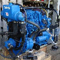
Again, the oil light can be seen on the dash, lit up in green. That's fed off the original switch, found above the filter. The gauge sensor is stuck in the back end of the block, to plug the hole would have fed the brake pump. You can see it painted black in the photos, below the black cam-shaft end cover. Where the gauges have a corresponding warning light, the light and gauge are on independent sensors, so I have some cover for a sensor failure.
Clearer view of the dash, before fitting
GoceKU wrote: 25 May 2020, 12:29 I think i have the same engine, but a bit older, come out of a 1983 peugeot 305 and the title says it's a 1905cc 47 kw unit
That would be the XUD9, the bigger 1.9L version. What's it used for? I can't make out the context of the photo, some kind of frame around it.
white exec wrote: 25 May 2020, 12:44 That's an interesting cast lump on the top of the rocker cover in your photo.
It looks like the rocker cover on the front of my Haynes Manual, but it has the Bosch fuel pump on it.
User avatar
moizeau
(Donor 2022)
Posts: 1580
Joined: 12 Jan 2015, 16:08
Location: France 36
My Cars: 91 BX TZD Estate. Dead but loved
407 HDI 136 auto
C4 2l petrol coupé
2010 Dispatch III HDI 90
AND a 1980 Z1000ST
AND a 1983 GPz1100 inj
AND a 1995 Zephyr 1100
AND a 1980 Z650 (my moped)
x 315

Re: My Engine

Post by moizeau »

The cold start 'wax bath' contraption isn't serviceable. I wouldn't worry about that until you've set the rest of the pump up. All it does is pull on the accelerator lever a tad to increase revs. My BX ran with a duff one for years, I just touched the acc pedal to lift the revs when cold. When you replace it, to set it up, warm the engine and you should have a 1mm or so of slack in the cable. When the engine is cold there is no slack because it's operating the lever.
If the leak you're referring to on the top of the pump is from the acc lever these can be replaced in situ. Remove the lever, hold the spline in place whilst you remove the top cover. If you're lucky a new viton 'o' ring will sort it although it has probably ovalled the recess. The top plates used to be available, not sure if they still are.
Pete
Notice the BX is still top the list but sadly gone
User avatar
white exec
Moderating Team
Posts: 7445
Joined: 21 Dec 2015, 12:46
Location: Sayalonga, Malaga, Spain
My Cars: 1996 XM 2.5TD Exclusive hatch RHD
1992 BX19D Millesime hatch LHD
previously 1989 BX19RD, 1998 ZX 1.9D auto, 2001 Xantia 1.8i auto
and lots of Rovers before that: 1935 Ten, 1947 Sixteen, 1960 P5 3-litre, 1966 P6 2000, 1972 P6 2000TC, and 1975 P6B 3500S
x 1752

Re: My Engine

Post by white exec »

A lot to digest there.

The alternator should not be running at half crankshaft speed! For decent output, an alternator needs to be running at around 2400rpm at idle, 6000rpm for full output, and not exceed 18,000rpm, according to a few web articles. This implies an alternator pulley size 1/3 of the diameter of the crankshaft one.

Not a good idea to feed the entire coolant flow through the oil cooler. They are not designed for high flow, and will be a constriction point. Not unusual for oil coolers to be plumbed in in parallel (i.e. across) the main radiator. This way, the larger part of the coolant flow goes through the radiator (typically through a 40mm bore hose), while a smaller hose (15-16mm bore) carries lesser flow through the cooler.

I wouldn't worry to much about the oil cooler being able to warm up engine oil from cylinder/block hot coolant. The important function is to get rid of heat from the oil, into the cooling system. So, if the oil cooler only operates on the radiator side of the thermostat, that's ok. The thermostat will quite happily run the block/head at its proper temperature, irrespective of anything downstream (can I say that?) of the thermostat.

I think the t-piece is not helping; as you say, better to provide two separate and controlled pathways. Important that the heater matrix is plumbed in directly across the block/head, so that it and the block/head operate as a small closed circuit (with the pump) when the therrmostat is closed. The heater matrix should always be at block/head temperature, for optimum and rapid cabin warmth.

If the alternator output for the tacho turns out to be really complicated, take another look at using the original flywheel type sensor. It can be run from the flywheel (can't remember of you have flywheel access now), or from somewhere else - eg crankshaft or connected gubbins. Does your tacho have an input suitable for a small-signal inductive pickup? (d.c. resistance of the Peu/Cit originals is 70-ohm, and they're easily available. Need to be approx 1mm from the rotating steel peg/gap; most are now made with a sacrificial 1mm nodule on the end, which is fitted in contact with the trigger, and is worn away by it.)

The resistance which accompanies many Charging dash lights is there solely to provide continuity in the event of bulb failure. Normally, the bulb filament itself provides the electrical link.

Morse throttle lever... I would be removing the lever, and drilling several additional holes towards the pivot point. That way you can make the lever less sensitive, and choose the best slot. As you sah, might be easier to extend the pump lever. Are you sure that pump is a Bosch? In your last photo it looks unfamiliar.
Chris
User avatar
XUD Marine
Posts: 54
Joined: 30 Jun 2019, 10:14
Location: North Lincs
My Cars: XUD7 1.8 Marine Engine
x 8

Re: My Engine

Post by XUD Marine »

As always, thanks for the insights.
moizeau wrote: 13 Dec 2020, 15:49 The cold start 'wax bath' contraption isn't serviceable. I wouldn't worry about that until you've set the rest of the pump up. All it does is pull on the accelerator lever a tad to increase revs. My BX ran with a duff one for years, I just touched the acc pedal to lift the revs when cold. When you replace it, to set it up, warm the engine and you should have a 1mm or so of slack in the cable. When the engine is cold there is no slack because it's operating the lever.
I suppose it is not too urgent and I can get by without it. I did have a look for them on-line though.
https://www.ebay.co.uk/itm/Idle-Control ... 3711932551
This looks like the kind of thing, though I'm not sure why a lot of listings refer to "air control", surely these control the fuel, not air.
moizeau wrote: 13 Dec 2020, 15:49 If the leak you're referring to on the top of the pump is from the acc lever these can be replaced in situ. Remove the lever, hold the spline in place whilst you remove the top cover. If you're lucky a new viton 'o' ring will sort it although it has probably ovalled the recess. The top plates used to be available, not sure if they still are.
The thought of dismantling the fuel pump seems daunting, but if it can be fixed fairly simply, by just removing the lever, I will have a go. I do have a set of spare O rings.
white exec wrote: 13 Dec 2020, 16:19 The alternator should not be running at half crankshaft speed! For decent output, an alternator needs to be running at around 2400rpm at idle, 6000rpm for full output, and not exceed 18,000rpm, according to a few web articles. This implies an alternator pulley size 1/3 of the diameter of the crankshaft one.
I think what I meant to say was double, not half speed. Though now you have me doubting if that is correct. I can always put another shiny sticker on it and find out.
white exec wrote: 13 Dec 2020, 16:19 Not a good idea to feed the entire coolant flow through the oil cooler. They are not designed for high flow, and will be a constriction point. Not unusual for oil coolers to be plumbed in in parallel (i.e. across) the main radiator. This way, the larger part of the coolant flow goes through the radiator (typically through a 40mm bore hose), while a smaller hose (15-16mm bore) carries lesser flow through the cooler.
Point taken. If I don't feed the cooler from the T on the heater port, I think the only other option is to drill a new hole in the thermostat housing. I think it has some blanks already, but I may have to tap a hole to make a pressure tight fitting.
Stat Housing, blank hole at the bottom
If I were to drill and tap into this blank at the bottom, I could screw a hose-tail in there. I think the ports in the cooler are only 16mm, so it doesn't need a big hose.
white exec wrote: 13 Dec 2020, 16:19 If the alternator output for the tacho turns out to be really complicated, take another look at using the original flywheel type sensor. It can be run from the flywheel (can't remember of you have flywheel access now), or from somewhere else - eg crankshaft or connected gubbins. Does your tacho have an input suitable for a small-signal inductive pickup? (d.c. resistance of the Peu/Cit originals is 70-ohm, and they're easily available. Need to be approx 1mm from the rotating steel peg/gap; most are now made with a sacrificial 1mm nodule on the end, which is fitted in contact with the trigger, and is worn away by it.)
I will have another go at getting it working from the alternator, probably after getting a speed reading from it to know the real ratio to the engine. But the TDC sensor is a back-up plan. The flywheel is pretty much covered by the new aluminium bell housing, but I could probably do something with the pump drive adaptor on the front pulley, as it is exposed and directly fastened to the crankshaft.
white exec wrote: 13 Dec 2020, 16:19 Morse throttle lever... I would be removing the lever, and drilling several additional holes towards the pivot point. That way you can make the lever less sensitive, and choose the best slot. As you sah, might be easier to extend the pump lever.
If I'm taking off the pump lever to fix the leak, I can maybe do a bit of work on it. I think If I have a measure up of the cable travel length, and the lever travel angle, I could calculate a new lever length. As I say, I may have to re-route the cooler pipes, but it looks like I will be draining the system too. So It may be an idea to get all that cooler/heater/thermostat stuff out of the way in one go while it's empty.
white exec wrote: 13 Dec 2020, 16:19 Are you sure that pump is a Bosch? In your last photo it looks unfamiliar.
I was referring to the beige engine that GoceKU posted. Its fuel pump is not like mine, so I assume it's the Bosch one. Mine is the Lucas. The picture on my manual has that style rocker top, but has a fuel pump like mine.
User avatar
moizeau
(Donor 2022)
Posts: 1580
Joined: 12 Jan 2015, 16:08
Location: France 36
My Cars: 91 BX TZD Estate. Dead but loved
407 HDI 136 auto
C4 2l petrol coupé
2010 Dispatch III HDI 90
AND a 1980 Z1000ST
AND a 1983 GPz1100 inj
AND a 1995 Zephyr 1100
AND a 1980 Z650 (my moped)
x 315

Re: My Engine

Post by moizeau »

When you take the top cover off the pump make sure you hold the spline in place whilst you lift, jiggle the cover...there are springs and things inside that you don't want to dislodge. Also mark the lever and spline so they go back in the same position.
Pete
Notice the BX is still top the list but sadly gone
Post Reply