Climate control sensor and fan

This is the Forum for all your Citroen Technical Questions, Problems or Advice.

Moderator: RichardW

User avatar
AndersDK
Posts: 6060
Joined: 21 Feb 2003, 04:56
Location: Denmark
My Cars:
x 1

Post by AndersDK »

Hehehe :lol:

This thread has been a real - oh yes - oh no - I think not - I think so.

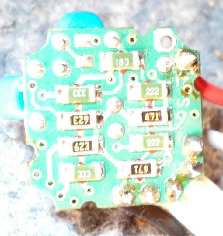
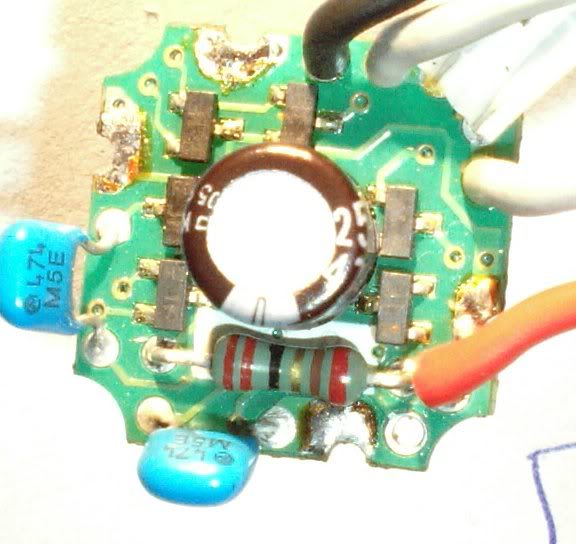
With that late close up of yours, we have finally closed in on the function. The tiny square black 3leads are either transistors or diodes. It looks pretty much whats inside a standard computer blower - if not exactly the same.
You wont be able to get a new PCB, nor will you be able to solder on these micro components. You need deep insight not to burn them out while soldering.

Go get a new computer fan - NOW.
Then stop further discussion on that burned out blower of yours.
You wont need that PCB on the new PC blower fan. Its build in - like I first explained.
All you need is to connect the new motor to your old motor leads, which are the red & black wire. New motor will come with black for minus and either red or yellow for the plus. The 2 white leads are the sensor. Doesnt matter which way around these 2 are connected.
Anders (DK) - '90 BX16Image
MikeT
Posts: 4809
Joined: 11 Jun 2007, 16:17
Location: Christchurch, Dorset. UK
My Cars: 2005 C5restyle 1.6HDI 16v 110hp VTR Estate
2008 C5 X7 1.6HDI VTR+ Saloon
x 231

Post by MikeT »

](*,)

So the answer is no (I can't test the motor seperately) then :lol:

Plan B was to try and source another motor that fitted inside the housing. Then I could add the fan onto the shaft. 8)

Plan C was to try and source a fan that could be bodged onto the housing but still fit behind the facia out of view.


Thanks for the advice AndersDK and sorry to carry this discussion on so much. :-#
RichardW
Forum Treasurer
Posts: 10872
Joined: 07 Aug 2002, 17:12
Location: United Kingdom
My Cars: MK2 '17 C4GP 1.6 BlueHDi 120
'13 3008 1.6 HDi GripControl
x 996

Post by RichardW »

Edit: Like wot Anders said :roll: Seems I can't even count 3 out of 4...

Mike,

My take on reading the Wiki article and your pics, is that the small PCB IS the motor controller, and you can't make the motor run without that PCB. I suspect you will find if you follow the sensor wires they will just 'pass through' the board. I suspect that one or more of the logic chips is fried and you will not be able to do anything with it (unless a coil is burnt out, or one of the permanent magnets is de-magnetised. The only solution I can think off (Other than forking out £85 for a new unit from Citroen) is buying a new motor complete with PCB and making a separate connection for the sensor.

Interesting stuff :lol:
Richard W
User avatar
CitroJim
A very naughty boy
Posts: 49621
Joined: 30 Apr 2005, 23:33
Location: Paggers
My Cars: Bluebell the AX, Polly the C3 Picasso, Pix the Nissan Pixo, Propel the duathlon bike, TCR Pro the road bike and Fuji the TT bike...
x 6183
Contact:

Post by CitroJim »

Mike,

I may be a bit too late here but before abandoning hope on this motor, check that big electrolytic. They're still, even in this day and age, one of the most unreliable components.

Also, the black things are just transistors. In other pieces of kit that use them I have successfully removed and replaced them using a decent fine-tipped soldering iron and a good sucker plus a bit of care.

They'll be power transistors as they form an oscillator to supply the motor an AC waveform.
Jim

Runner, cyclist, time triallist, duathlete, Citroen AX fan and the CCC Citroenian 'From A to Z' Columnist...
User avatar
CitroJim
A very naughty boy
Posts: 49621
Joined: 30 Apr 2005, 23:33
Location: Paggers
My Cars: Bluebell the AX, Polly the C3 Picasso, Pix the Nissan Pixo, Propel the duathlon bike, TCR Pro the road bike and Fuji the TT bike...
x 6183
Contact:

Post by CitroJim »

Mike,
Sorry, should have popped this in the post above.

can you try making a rough sketch of the circuit? The transistors will have their base on the single pin side of the package and looking at it with the base at the top, the two lower pins will most likely be emitter and collector. A quick test with an AVO will confirm if that is so and if they're NPN or PNP. Knowing Citroen they'll be PNP :roll:

You'll most likely find the motor coil forms part of the oscillator tuned circuit.

If we have a rough sketch of it we can all see how it works and perhaps find possible repair options.
Jim

Runner, cyclist, time triallist, duathlete, Citroen AX fan and the CCC Citroenian 'From A to Z' Columnist...
MikeT
Posts: 4809
Joined: 11 Jun 2007, 16:17
Location: Christchurch, Dorset. UK
My Cars: 2005 C5restyle 1.6HDI 16v 110hp VTR Estate
2008 C5 X7 1.6HDI VTR+ Saloon
x 231

Post by MikeT »

RichardW wrote:Edit: Like wot Anders said :roll: Seems I can't even count 3 out of 4...

Mike,

My take on reading the Wiki article and your pics, is that the small PCB IS the motor controller, and you can't make the motor run without that PCB
Agreed
I suspect you will find if you follow the sensor wires they will just 'pass through' the board
I agree. I tried looking for the tracks the sensor wires connect to but there doesn't seem to be anything visible so can't tell...yet
The only solution I can think off (Other than forking out £85 for a new unit from Citroen) is buying a new motor complete with PCB and making a separate connection for the sensor.
That was my plan B or C. If I can find a small enough motor and I can fit the fan blade rotor to it I'll have a direct replacement 8)

If not, I think a common "hard drive" fan should be small enough to fix onto the original housing
MikeT
Posts: 4809
Joined: 11 Jun 2007, 16:17
Location: Christchurch, Dorset. UK
My Cars: 2005 C5restyle 1.6HDI 16v 110hp VTR Estate
2008 C5 X7 1.6HDI VTR+ Saloon
x 231

Post by MikeT »

citrojim wrote:Mike,

I may be a bit too late here but before abandoning hope on this motor, check that big electrolytic.

You mean test it? I don't know how but I'll look it up if it'll help
Also, the black things are just transistors. In other pieces of kit that use them I have successfully removed and replaced them using a decent fine-tipped soldering iron and a good sucker plus a bit of care.
I could manage that maybe- always worth a try at least. I just didn't think surface-mount components could be purchased so easily.
MikeT
Posts: 4809
Joined: 11 Jun 2007, 16:17
Location: Christchurch, Dorset. UK
My Cars: 2005 C5restyle 1.6HDI 16v 110hp VTR Estate
2008 C5 X7 1.6HDI VTR+ Saloon
x 231

Post by MikeT »

citrojim wrote:Mike,
can you try making a rough sketch of the circuit?
Yes, I'll give it a go though I'd probably have to desolder it completely to get a clear layout view - it's double-sided.
A quick test with an AVO will confirm if that is so and if they're NPN or PNP. Knowing Citroen they'll be PNP :roll:
Again, don't know how exactly... I will read up on testing methods.
User avatar
AndersDK
Posts: 6060
Joined: 21 Feb 2003, 04:56
Location: Denmark
My Cars:
x 1

Post by AndersDK »

The 3 characters stamped on the transistors designates the type. I.e. translates to a more common BCxxx or 2Nxxxx transistor type, or a 1Nxxxx diode type.
Cant remember how to find these translation tables right now - but they are defo available on the web.

The transistors/diodes in your circuit are SMD (surface mount device) types. The lytic cap is just a ripple cap, not significant for the function. The circuit is some kind of a simple 2transistor multivibrator to create the needed alternating voltage for the small field coil in the motor. The 2 equal small caps are timing caps for each transistor in the multivibrator circuit. Together with the motor coils inductances they make up the 2 equal timing circuits needed.

If you really want a go (hehehe !) on repair, then start by checking the coil resistance. The coil dont "burn" out but disrupts because of the temp variations over its lifetime. The wounded wire simply snaps somewhere in the coil.
Anders (DK) - '90 BX16Image
MikeT
Posts: 4809
Joined: 11 Jun 2007, 16:17
Location: Christchurch, Dorset. UK
My Cars: 2005 C5restyle 1.6HDI 16v 110hp VTR Estate
2008 C5 X7 1.6HDI VTR+ Saloon
x 231

Post by MikeT »

Image


I hope this is clear enough.

On the opposite side are....

2x blue cap.s 474 M5E
1x black cap 25V 47uf (micro?farads)
1x resistor RED RED BLACK GOLD BROWN RED (forgotten my colour codes)
MikeT
Posts: 4809
Joined: 11 Jun 2007, 16:17
Location: Christchurch, Dorset. UK
My Cars: 2005 C5restyle 1.6HDI 16v 110hp VTR Estate
2008 C5 X7 1.6HDI VTR+ Saloon
x 231

Post by MikeT »

Image


As if on a spit, I rotated the board on it's horizontal axis so the top blue cap is now the bottom blue cap :!:

(Attempting) reading the left line of 3x transistors(?) top to bottom....

The first two characters are smaller font than the second two

H3 1F
F6 3F
H3 1F

The upper middle value is

F6(?) 3F

The 2x on the right side both

H3 1F


Have I left anything out?
User avatar
AndersDK
Posts: 6060
Joined: 21 Feb 2003, 04:56
Location: Denmark
My Cars:
x 1

Post by AndersDK »

Nope its all there now -
Go on searching for those type codes. My memory is stuck on the first SMD types which had 3 characters for type numbers. But later types will of course have newer demands on the codes to cover the vast range of component types available - since I was young :lol:

But I'd certainly for long switched track against the PC fan blower approach 8)
I dont fancy having glasses on with 5x gain and my shaking old hands trying to hit the right part with a pen-soldering iron. Thats really past my kind of a fun party :lol: :lol:

EDIT : the small square bits with a 3digit number on are resistors. The value is read by the number code. Last digit in the code denotes 10's multiplier. I.e 0 = 10in0 (= x1), 1 = 10in1 (= x10), 2 = 10in2 (=x100) etc
First 2 digits are the basic value.

blue caps 474 are read the same way by units in picoFarad, which then translates to 470,000pico(p) or 470nano(n) or 0.47micro(µ) -Farad
M5E is a classification code

Color codes
black = 0, brown = 1, red = 2, orange = 3, yellow = 4, green = 5, blue = 6, violet = 7, grey = 8, white = 9.
Thats on the backbone of any electronics engineer, like the morse code is on the backbone of any radio amateur 8)

I wont get into details on all the possible code variants on the colors, by their location on the component.
1x resistor RED RED BLACK GOLD BROWN RED
would translate to basic value 220 and then with the 10's multiplier for gold, which is 10in-1 (x0.1).
Which then finally equals 22 ohms.
remaining 2 color rings are usually precision and temp classes on the resistor (but not wattage, which will go by the body size or directly reading code i.e 1W for 1watts)
Last edited by AndersDK on 18 Jul 2007, 21:20, edited 1 time in total.
Anders (DK) - '90 BX16Image
MikeT
Posts: 4809
Joined: 11 Jun 2007, 16:17
Location: Christchurch, Dorset. UK
My Cars: 2005 C5restyle 1.6HDI 16v 110hp VTR Estate
2008 C5 X7 1.6HDI VTR+ Saloon
x 231

Post by MikeT »

183=18K
333=33K
623=62K
222=2200
471=470
MikeT
Posts: 4809
Joined: 11 Jun 2007, 16:17
Location: Christchurch, Dorset. UK
My Cars: 2005 C5restyle 1.6HDI 16v 110hp VTR Estate
2008 C5 X7 1.6HDI VTR+ Saloon
x 231

Post by MikeT »

Did I read the other numbers in the right order or should they be...?

1F H3
3F F6

If 1F is the code, this is the lookup

1F BC847B Phi N SOT23 BC547B
1F BC847BT Phi N SOT416 BC547B
1F MMBT5550 Mot N SOT23 2N5550 140V npn

If 3F is the code, this is the lookup

3F BC857B Phi N SOT23 BC557B
3F BC857BT Phi N SOT416 BC557B
3F- BC857BW Phi N SOT323 BC557B

I think I did get them the wrong way round first time; there is no F6 equivalent otherwise H3 is...

BCW89
User avatar
AndersDK
Posts: 6060
Joined: 21 Feb 2003, 04:56
Location: Denmark
My Cars:
x 1

Post by AndersDK »

first 2 characters would be type no, next 2 would be the maker. Does that make sense ?

Anyway the BC847 and BC857 are about the most common types for general purpose SMD transistors, so that cant be wrong.
They are equivalent to the BC547 and and BC557 types, which likewise ar the common or garden types in almost any discrete application. Only difference are the leads and package type.

Honestly Mike - we are way off topic now :roll:
Anders (DK) - '90 BX16Image
Post Reply